Automatic Transmission Hydraulics
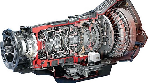
Hydraulics, sometimes called fluid power, refers to the use of fluid to transmit motion and force. The key principle behind hydraulics is that fluids are not compressible. Because of this property, automatic transmissions can rely on pressurized fluid—directed and managed by electronic controls—to transfer power and operate the gears effectively.
At the heart of the system is the transmission pump, which delivers pressurized fluid throughout the entire transmission. This includes supplying fluid to the torque converter, valve body, clutches, bands, cooler, and lubrication passages. Without this constant circulation of fluid, none of the transmission’s major components could perform their assigned tasks.
Within the hydraulic system, there are two primary circuits: the high-pressure circuit and the lubrication circuit.
The high-pressure circuit contains the components that manage gear shifting, including the valve body and various shift elements. These regulate hydraulic pressure so that the clutches and bands apply with precision during gear changes.
The lubrication circuit, on the other hand, ensures smooth operation and heat management. It includes the transmission cooler, thermostat, lubrication passages, and the torque converter, all of which keep components from overheating and wearing prematurely.
One of the best examples of power transfer through fluid pressure is the torque converter, where hydraulic force is used to multiply torque and transfer power between the engine and the transmission. This important component will be explained more thoroughly in another chapter.
Another major use of hydraulics inside the transmission is in the application of multi-disc clutches. Pressurized fluid applies these clutches to either hold or rotate specific members of the planetary gear sets, which in turn routes power through the gear train.
This chapter will focus on exactly that: how hydraulic pressure is used to control power flow through the automatic transmission’s gear train.
Fluid Motion
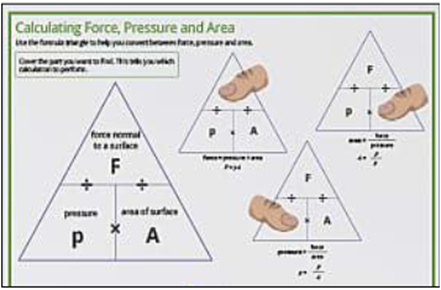
The formula used to calculate fluid force is:
Force = Pressure × Area
This is known as Pascal’s Law, which states:
"When force is applied to a liquid confined in a container, the pressure is transmitted equally and undiminished in every direction."
At first glance, this looks like a simple algebraic equation, but it is one of the most powerful concepts in hydraulics. Figure 1 illustrates how this formula can be applied when any two of the three values are known.
|  |
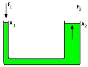
To better appreciate the power of fluid motion, look at Figure 2. This diagram shows how Pascal’s Law makes it possible to lift a car. When a force is applied to the smaller piston (A1), it produces pressure that is transmitted to the larger piston (A2). If the larger piston has ten times the surface area of the smaller one, the resulting force at F2 will be ten times greater than the input force at F1. In other words, a relatively small effort applied at one end can multiply into a very large lifting force at the other end—enough to raise a vehicle. | 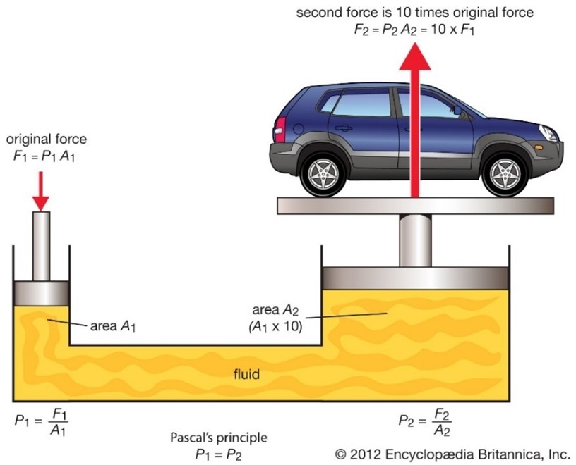 |
Since fluids cannot be compressed, any pressure applied at one point is transmitted fully throughout the system. An additional benefit is that fluids conform to the exact shape of their container or passageway, allowing them to reach every corner of the hydraulic circuit.
Figure 3 demonstrates how this principle is applied in practice. Imagine an electric motor applying a 625 lb. force to piston A1, which has an area of 0.75 in². Using Pascal’s Law:
Now, if piston A2 has an area of 12 in², we can calculate output force:
This is nearly 10,000 lb.—enough to lift most passenger cars and many light-duty pickup trucks. In fact, this is why many vehicle lifts are rated at 10,000 lb. Notice from this example that the larger the difference in size between the input piston and the output piston, the greater the multiplied force. | 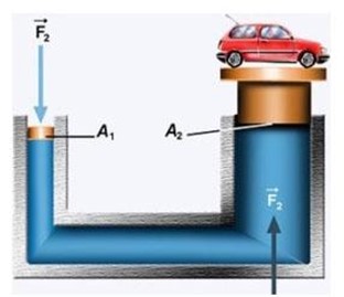 |
Now let’s work through another example that is more directly related to transmissions. Suppose piston A1 has an area of 0.50 in², and the applied force is 100 lb.
Pressure = Force ÷ Area
100 lb. ÷ 0.50 in² = 200 psi.
This is the pressure generated within the hydraulic circuit. If piston A2 has an area of 3 in², then:
Force = Pressure × Area
200 psi × 3 in² = 600 lb. of output force.
This is the amount of force acting on a multi-disc clutch assembly to compress the clutch plates tightly enough to prevent slippage. In other words, hydraulic pressure multiplication gives the transmission the holding capability it needs for proper clutch and band engagement.
For extra practice, consider Figure 4: If piston A1 has an area of 2 in², and the force applied at F1 is 300 lb., then:
If piston A2 has an area of 4 in², then output force is:
|  |
This final example reinforces a key principle: hydraulics makes it possible to take a relatively small input force and multiply it into the much larger forces required for automatic transmission operation.
Multi-disc Clutches
Multi-disc clutch assemblies were designed to achieve high holding capacity within a compact space. Instead of relying on a single large-diameter disc, engineers placed several smaller clutch discs inside a drum, creating multiple surfaces of contact. The result is a clutch pack with much greater holding ability while still fitting inside the limited space of a transmission. When one of these clutches is applied, it either drives or holds a member of the planetary gear set, allowing power to be routed through the transmission.
However, clutch application is not as simple as just applying hydraulic pressure. Many engineering factors must be taken into account, including vehicle weight, clutch diameter, and the level of pump pressure available. For example, a heavier vehicle requires higher clamping pressure for its clutches to hold properly. Likewise, the number of discs in a clutch pack directly affects its holding capacity—the more discs, the greater the surface area, and therefore the greater the holding force.
Other design considerations include:
The friction coefficients of the steel and friction plate materials,
The lubricity of the transmission fluid, and
The maximum hydraulic apply pressure the system can generate.
For our purposes, the key point is this: multi-disc clutch assemblies provide a large surface contact area, and this is what enables them to achieve the strong holding power needed in automatic transmissions.
Keep in mind that multi-disc clutches are just one part of the system that must reliably propel vehicles of all sizes—from a small 3,500 lb. car to a 9,000 lb. pickup truck. Despite the wide range of demands placed on them, these clutches perform their work with impressive dependability. | 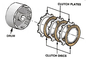 |
The accompanying video illustrates several important steps in rebuilding a multi-disc clutch:
Friction discs are pre-lubricated before assembly.
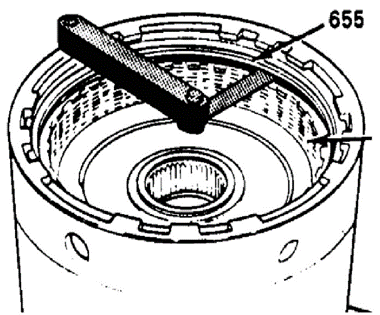
Friction and steel plates are stacked together, with an end plate and snap ring installed to secure the pack.
Clutch clearance is measured using a feeler gauge.
Finally, the three clutches inside the input drum are “air checked.”
Performing an air check on clutches and piston assemblies before the transmission is reinstalled in a vehicle is a smart practice. It allows any issues to be discovered early in the rebuild, rather than during the first road test after installation.
(Note: The video is queued to begin at 26:00 and ends at 31:04.)

Below is an ASE (Automotive Service Excellence) practice question about multi-disc clutch clearance. All clutches need to have some clearance in between the steel and friction plates, so they can be lubricated and free whenever the clutch is not engaged. See if you have an understanding of how to measure multi-disc clutch clearance by answering this question.
Question: Clutch clearance on a multi-disc clutch is being measured. A stack of feeler gauges totaling 0.081 in. fits between a steel plate and a friction disc. The specification for this clutch is 0.055–0.075 in. The original pressure plate measures 0.110 in. thick. Service information lists three optional replacement plate thicknesses available: 0.122 in., 0.138 in., and 0.145 in.
Which replacement plate will bring the clutch clearance back into specification?
0.122" plate
0.138" plate
0.145" plate
Transmission Bands
Before we talk directly about transmission bands, let’s briefly consider the role of seal rings. Seal rings are used to create fluid-tight passages inside the transmission. Their job is to channel pressurized fluid to various components—such as a clutch drum—so that hydraulic force can be applied precisely where it is needed.

Now let’s shift focus to the transmission band. Figure 7 includes two images that help explain how bands work.
Also notice in the bottom image that there is an adjusting screw located on the right-hand side. This threaded screw serves as the adjustable anchor that holds the opposite end of the band securely in place during operation. | 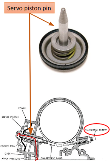 |
Sometimes, transmission bands must be adjusted to restore proper shift quality. Band adjustment was once a very common maintenance procedure, particularly with older three- and four-speed automatic transmissions. In contrast, modern six-, seven-, eight-, nine-, and ten-speed units rely far less on bands, as newer designs favor clutches and electronic control strategies instead.
To better understand band adjustment in practice, watch the short segment provided from a Dodge 46RE four-speed transmission rebuild. The video shows how a band is adjusted, and you only need to watch about two minutes of footage (from 41:35 to 43:35).
Transmission Pumps
The pump is the starting point of fluid flow inside an automatic transmission. As shown in Figure 8, the pump draws fluid from the sump (the transmission pan), where it is first filtered. From there, some of this fluid is directed immediately into the torque converter. This flow is called converter charge oil, and it is essential because the torque converter must remain filled with fluid in order to transfer engine torque into the transmission. In addition to feeding the torque converter, fluid is also routed (though not shown here) into the control valve assembly, or valve body, where hydraulic circuits are regulated.
Not every transmission has a serviceable filter like the one shown in the diagram. Rear-wheel-drive (RWD) transmissions typically include a pan and a replaceable filter. Front-wheel-drive (FWD) transaxles, however, are often designed differently. Many do not have a bottom pan or an external filter. Instead, they feature a side cover for accessing the valve body and solenoids, but the filter itself is generally non-serviceable—it can only be replaced when the transaxle is fully disassembled. | 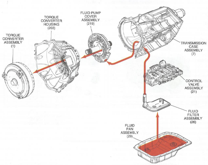 |
A transmission pump’s role is to supply fluid to all hydraulic circuits, including both the high-pressure and lubrication circuits. If the pump fails, the transmission will not operate because hydraulic pressure is the lifeblood of automatic transmission function.
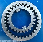
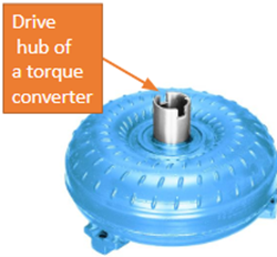
All transmission pumps are mechanically driven by the engine. The center gear of the pump (see Figure 9) has two drive lugs that engage with the torque converter’s drive hub. The hub itself (shown in Figure 10) contains two square notches that match perfectly with the pump’s gear lugs. This direct connection ensures that whenever the engine is running, the pump gears turn.
This design provides immediate fluid pressure as soon as the engine starts, allowing the transmission to engage Drive or Reverse without delay.
For example, Figures 11 and 12 show an off-set pump design from a Ford 10R80 transmission. The gear located in the transmission’s front cover (highlighted with a red arrow in Figure 11) is driven by the torque converter. That gear then drives a second gear, which in turn drives the pump mounted off to the side. Altogether, there are three gears: the torque converter-driven gear, the secondary gear, and the pump’s own drive gear. This off-set arrangement has become very common in today’s transmission designs. Figures 11 and 12 When discussing transmission pumps, there are two main types to consider:
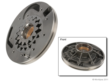
Gear-type pumps were the standard for decades, especially during the era of three-speed and four-speed transmissions. They are simple, durable, and reliable, but they have one limitation: they deliver a constant displacement of fluid. In other words, they always pump the same volume of oil regardless of conditions, even when less flow would be sufficient. Variable vane pumps, on the other hand, are far more common today. These pumps are capable of variable displacement, meaning they adjust their output based on operating needs. This not only reduces drag on the engine during light load or low RPM conditions, but also ensures adequate oil flow for lubrication and cooling even when pressure is low. | 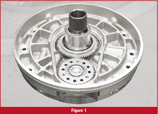 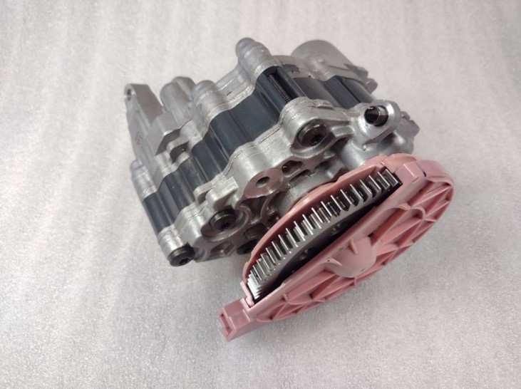 |
In the past, constant displacement pumps were favored for their ruggedness. Built with cast-iron housings and steel gears, they were exceptionally durable. However, their inability to vary output made them less efficient compared to modern needs. Variable vane pumps, while typically using an aluminum housing, still employ steel for all their internal moving parts, striking a balance between efficiency and durability.
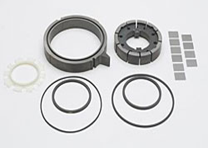

Variable Vane Pumps
The video below demonstrates several transmission pump designs and shows how to measure pump component wear using a feeler gauge and a straight edge. It also introduces the H gauge, explaining what it is and how to use it correctly. For transmission rebuilders, mastering these tools and procedures is essential.

At the core, all pumps function on the principle of creating high- and low-pressure areas. As the pump rotates, the intake side forms a slight vacuum or void, which allows atmospheric pressure to push transmission fluid into the intake area. The vanes then draw this fluid into larger cavity spaces. As the fluid moves along, it is forced into smaller cavity areas, where it becomes compressed. This compression produces higher-pressure fluid that exits through the discharge port. Because the pump is constantly forming alternating low- and high-pressure areas, the system naturally produces pulsations. This explains why, when measuring transmission pressure, the gauge needle often vibrates or oscillates slightly instead of holding perfectly still. | 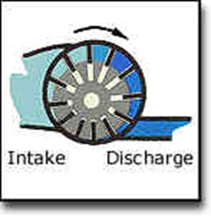 |
Diagnostic Considerations for Pumps
Several conditions related to pumps are important to recognize during diagnosis:
A failing or damaged pump may create a noticeable noise whenever the engine is running. Normally, pumps should operate quietly.
If a pump ceases to function, the transmission itself will stop operating.
Low hydraulic pressure output may result from a weak pump, though other issues can also contribute, such as low fluid level, a leaking clutch piston seal, or worn shaft seal rings.
A leak anywhere in the hydraulic system causes a pressure drop throughout the entire system, not just at the leak point.
Figure 17 illustrates a variable vane pump. In this example, fluid is drawn through the filter from the sump or pan, pressurized by the pump, and then delivered into the “LINE” passage. This passage is referred to as the main line pressure.
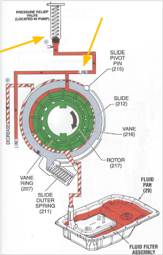
All hydraulic circuits within the transmission originate from this main line pressure. Depending on where the fluid travels within the transmission, pressures are modified to provide the correct force to specific components.
At the top of Figure 17, note the round black ball and spring. This is the pressure relief valve. Its purpose is to protect the system by opening whenever pressure rises too high, allowing excess fluid to “blow off” back into the pan.
Pressure regulation is primarily handled in the valve body through a solenoid known as the EPC, or Electronic Pressure Control Solenoid. Different manufacturers use different terms for this solenoid—for example, some call it the LPC (Line Pressure Control) solenoid, while older General Motors units referred to it as a Force Motor.
Both constant volume and variable vane pumps utilize EPC/LPC solenoids. While gear-type pumps provide a fixed fluid volume with every rotation, vane pumps can vary their output. The EPC solenoid enables the transmission control module (TCM) to regulate pump pressure by using input from sensors such as the MAP (manifold absolute pressure), TPS (throttle position sensor), and sometimes the MAF (mass air flow) sensor.
The EPC’s main responsibility is to adjust clutch and lube pressures, effectively governing how the transmission feels during a shift. In other words, it fine-tunes “shift feel.”
Vane pumps have an important advantage in this area. They can supply strong fluid volume even at low engine speeds, ensuring the lubrication circuit always receives enough oil to prevent overheating or damage. Constant volume pumps, in contrast, may starve the lubrication circuit at low rpm, creating a risk of overheating or premature wear.
Constant displacement pumps also lack the efficiency of vane pumps. Because they always move the same volume of fluid proportional to pump speed, they create more drag on the engine, especially under light-load conditions. Vane pumps, however, can reduce resistance when demand is low, which improves engine efficiency.
In short, the hydraulic system must carefully balance two things: delivering enough fluid volume for lubrication and applying the correct hydraulic pressure to clutches for smooth operation. Variable vane pumps, combined with EPC solenoids, are the modern solution that allows transmissions to achieve this balance effectively.
The moment the engine fires up, the transmission pump begins turning, generating hydraulic pressure throughout the system. This pressure, however, must be carefully regulated for the transmission to function properly. That task falls to the Pressure Regulator Valve (PR valve). Working together with its spring and the LPC/EPC solenoid, the PR valve ensures that line pressures are kept within precise operating ranges.
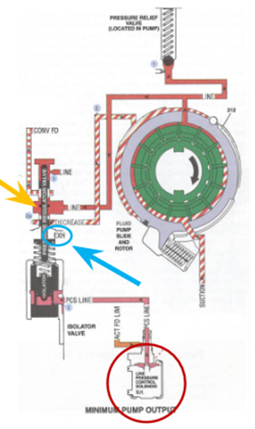
The PR valve operates on a balance of forces. On one side, pump pressure constantly pushes against the valve. On the other, a calibrated spring provides resistance. As pump pressure increases to a certain point, the valve shifts in its bore, momentarily opening a passage to exhaust excess pressure (circled in blue in Figure 18). This cycling happens several times per second, creating a steady and reliable line pressure.
Typical main line pressure values include:
At idle or steady cruise: 50–120 psi
During open-throttle acceleration: 90–160 psi
In reverse: 150–300 psi (depending on throttle position)
The LPC solenoid (Line Pressure Control, also known as EPC—Electronic Pressure Control) fine-tunes this balance. Controlled by the Transmission Control Module (TCM), the solenoid receives electrical current ranging from about 0.10–1.20 amps.
When more current is applied, the solenoid’s magnetic field strengthens, pulling the PR valve toward it. This reduces output pressure.
When less current is applied, the solenoid’s magnetic pull weakens, allowing the spring to push the valve back. This raises line pressure.
By constantly adjusting the valve’s position, the LPC solenoid can quickly and smoothly regulate pressure, which directly influences how the clutches apply. In practical terms, this is what gives a modern automatic transmission its smooth, refined shift feel under different engine load conditions.
If the LPC solenoid fails or loses power, the system defaults to maximum line pressure. When this happens, the transmission will still shift, but shifts will be harsh and abrupt because full pressure is being applied to the clutches without modulation.
Variable Vane Pump Components
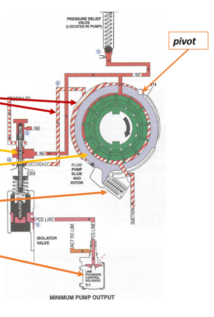
Take time to study Figure 19 so you can become familiar with the major components of a variable vane pump and where each one is located.
|  |
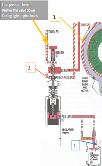
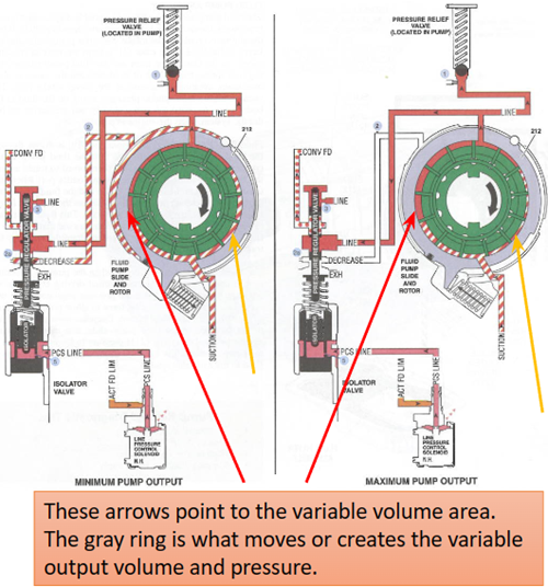
The LPC solenoid exhausts fluid in order to regulate the PCS line (the pink-colored circuit).
As this happens, the regulator valve moves downward, which allows line fluid to enter the decrease circuit.
Decrease oil then flows in behind the gray slide ring, adjusting the pump’s volume and pressure output.
The further the regulator valve moves downward, the more line pressure is admitted into the decrease circuit. This pushes the slide ring farther, which alters the pump’s displacement. These adjustments are constantly made in response to changes in engine torque load.
The Transmission Control Module (TCM) is in charge of this process. It commands the LPC solenoid based on two main inputs:
|  |
Finally, examine the pivot point in Figure 22. This is where the slide ring pivots whenever decrease fluid pushes on its outer edge.
During minimum output conditions, the PR valve (green arrow) allows decrease fluid to act on the slide’s outer side. This reduces pump displacement and lowers output pressure. Conversely, when decrease fluid is reduced, the spring moves the slide back, increasing pump output. | 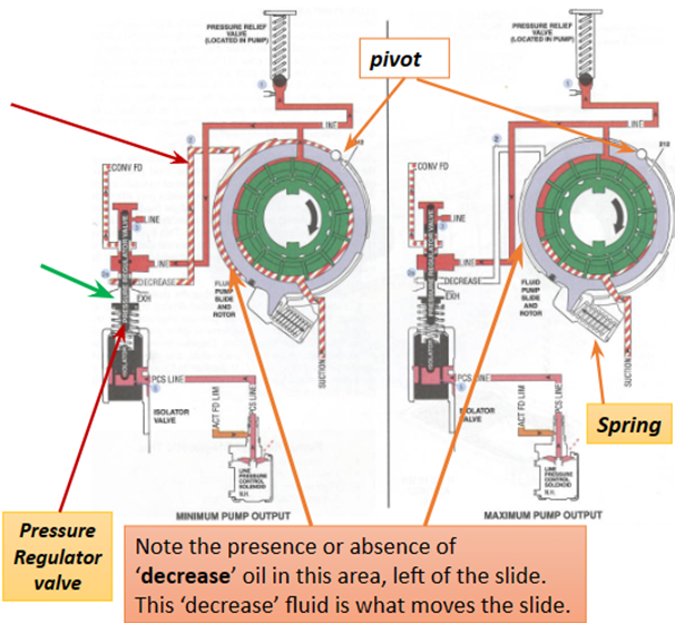 |
The Valve Body
Now let’s shift our focus to the valve control assembly, more commonly referred to as the valve body. This highly complex component functions as the hydraulic control center of an automatic transmission. While its design can vary depending on the transmission type, valve bodies are found not only in traditional automatics but also in some CVTs and dual-clutch units.
The job of the valve body is to direct hydraulic fluid to the correct clutches (and to bands, if the transmission uses them) so they can apply and release at the proper time. By doing this, the valve body enables the transmission to shift between gear ratios smoothly and efficiently.
The hydraulic system begins with the transmission pump, which produces the fluid pressure needed to operate the system. The valve body then acts as the command center of the high-pressure circuit. Its many passages, valves, and solenoids route that fluid exactly where it needs to go.
The solenoids within the valve body are controlled by the Transmission Control Module (TCM). The TCM uses electronic signals to operate these solenoids, which in turn regulate hydraulic pressure and fluid flow. By managing this precisely, the TCM is able to time the apply and release of clutches to achieve smooth gear changes.
The video you’ll view provides a clear example of this process. It shows how transmission fluid moves from the sump (pan), through the valve body, and into the 1–2 shift valve and solenoid. Even though the demonstration focuses on just one shift event (the 1–2 shift), it illustrates the complexity of how hydraulic and electronic systems work together.

Keep in mind, though, that what you saw in the video represents only a fraction of what’s really happening inside a valve body. For each gear change, multiple valves move in their precision-machined bores, reacting against calibrated springs and responding to solenoid commands from the TCM. This entire process is a remarkable example of both hydraulic engineering and electronic programming, working seamlessly to create predictable, reliable shifts.
A key part of many valve bodies is the separator plate. Not all transmissions use one, but when present, it serves a vital function. The separator plate is a thin sheet of steel with a carefully designed pattern of round and rectangular holes.
Some of the round holes are drilled to precise diameters and function as orifices, metering fluid flow from one passage to another.
At the same time, the plate acts as a gasket, sealing adjacent passages from each other so fluid only flows where it’s intended.
By combining flow control with sealing, the separator plate ensures that the hydraulic circuits operate exactly as designed.
In short, the valve body is the “brain of the hydraulic system.” It takes the fluid pressure supplied by the pump, and under the TCM’s guidance, routes that pressure to apply the right clutch or band at the right moment. Without the valve body, an automatic transmission would simply not be able to function.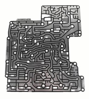
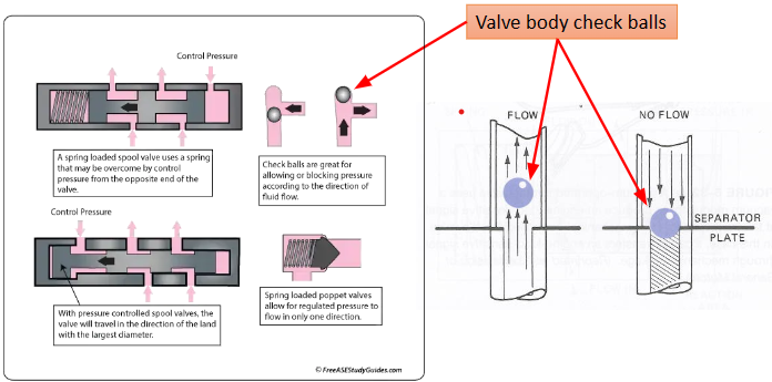
Many transmission valve control assemblies require the use of check balls, which are usually made from steel or a very durable plastic. Check balls serve as one-way fluid gates: they allow hydraulic fluid to flow in one direction during a particular shift, and then they block fluid flow when pressure is applied in the opposite direction during another shift. This simple but effective design ensures precise routing of hydraulic fluid during multiple gear changes.
Manual Valves and Rooster Combs
The next key components are the manual valve and the rooster comb. These work together to help determine gear selection. The manual valve is mechanically connected to the driver’s shift lever, while the rooster comb interfaces with the valve and other components such as the shift cable and the MLP (Manual Lever Position) switch. The MLP, also called the Transmission Range Switch (TRS), communicates gear selection to the vehicle’s electronics.
Older valve body designs often required adjustment of the shift cable and TRS to ensure correct alignment and smooth operation. The first video assigned here explains how the manual valve and rooster comb function, as well as the importance of proper adjustments.

Drive-by-Wire Systems
Not all modern transmissions use a manual valve. For example, the Ford 10R80 and many other eight, nine, and ten-speed transmissions use drive-by-wire technology. Instead of a direct mechanical connection, electronic signals communicate driver input to the transmission. This “shift-by-wire” system eliminates the manual valve entirely. The second video you’ll watch demonstrates how the 10R80 operates without a manual valve, giving you a sense of how modern electronic control has replaced older mechanical systems.

Solenoids and Fluid Control
Just as we saw in the 4L60E 1–2 shift video, when the Transmission Control Module (TCM) determines it is time for a shift, it operates one or more solenoids. Depending on the design, the TCM either completes a ground or supplies power to the solenoid.
Solenoids come in two main types:
Normally Open (NO), also called Normally High (NH): These solenoids allow fluid to pass through to a hydraulic circuit when they are at rest (not energized). When activated, they close off the circuit.
Normally Closed (NC), also called Normally Low (NL): These solenoids block fluid flow when they are at rest. When activated, they open and allow pressure to pass through.
In short, a solenoid either blocks or permits fluid flow, depending on its type and whether or not the TCM has energized it.
Evolution of Valve Body Design
Valve body design has changed significantly over the years. Older four-speed transmissions had valve bodies that were mechanically complex: they contained numerous valves and springs but only a few solenoids. In contrast, modern six- to ten-speed transmissions use valve bodies that are electronically complex: they rely on more solenoids but have fewer physical valves and passages. This makes them simpler in hydraulic layout, but more expensive due to the electronic components.
Switch Valves and Solenoid Application
One important type of valve used in modern valve bodies is the switch valve. As shown in Figure 25, when a solenoid sends pressure to one end of the valve (red arrow), the valve moves against spring force. This opens a passage and directs hydraulic pressure to a shift element such as a clutch. | 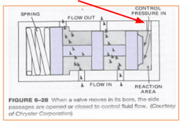 |
To better understand how solenoids function in practice, look at the GM 8L90 solenoid application chart in Figure 26. Notice that:
Solenoids S1, S4, and S5 are normally open (NO), which means they always allow pressure flow unless energized to close.
Solenoids S2, S3, S7, S8, and S9 are normally closed (NC), which means they block pressure flow until energized to open.
This chart is a perfect example of how solenoid logic is programmed into a transmission. The TCM selectively energizes solenoids to open or close passages, allowing the correct clutches to apply at just the right time.
| Range | Gear | S1 (NH) 1-2-7-8 Reverse | S2 (NL) 1-2-3-4-5 Reverse | S3 (NL) 1-3-5-6-7 | S4 (NH) 2-3-4-6-8 | S5 (NH) 4-5-6-7-8 Reverse | S7 (NL) TCC | S8 (NC) Default Control | S9 (NC) 1-2-3-4-5 |
| Park | P | On | On | Off | Off | Off | Off | Off | Off |
| Reverse | R | On | On | Off | Off | On | Off | Off | Off |
| Neutral | N | On | On | Off | Off | Off | Off | Off | Off |
| Drive | 1st | On | On | On | Off | Off | On° | Off/On | Off |
| 2nd | On | On | Off | On | Off | On° | Off/On | Off | |
| 3rd | Off | On | On | On | Off | On° | Off* | Off | |
| 4th | Off | On | Off | On | On | On° | Off* | Off | |
| 5th | Off | On | On | Off | On | On° | Off* | Off | |
| 6th | Off | Off | On | On | On | On° | Off* | On | |
| 7th | On | Off | On | Off | On | On° | Off* | On | |
| 8th | On | Off | Off | On | On | On° | Off* | On |
NOTE: Off = Solenoid control port not pressurized.
Off/On = soleinoid control port is not pressurized at low speed in 1st gear, solenoid control port is pressurized at high speed in 1st gear.
On/Off = soleinoid control port is pressurized at low speed in 2nd gear, solenoid control port is not pressurized at high speed in 2nd gear.
* = Default valve is hydraulically latched in the stroked position in this state, default solenoid can be commanded on for lube override.
° = The TCC may apply from 1st through 8th gear depending upon shift condition determined by the TCM
Figure 26
Key takeaway: Check balls, manual valves, rooster combs, and solenoids all serve the same ultimate purpose—directing hydraulic fluid to the right place at the right time. The way they accomplish this has evolved from mechanical pathways (older valve bodies) to electronically controlled systems (modern drive-by-wire transmissions), but the principle of fluid control remains the same.
Failsafe Mode and Valve Types
A transmission also has what is known as failsafe mode. In this mode, the transmission operates with only one forward gear and usually reverse. For the GM 8L90, the default failsafe gear is 2nd gear. Its hydraulic design ensures that even if none of the solenoids are activated by the TCM, 2nd gear can still be applied hydraulically.
There are three basic types of valves used in transmissions: switch valves, regulator valves, and servo valves. These designs have been in use for many years.
Switch valves function like electrical switches, either blocking or allowing fluid to pass. Also referred to as shift valves, they can direct fluid to a clutch, send fluid to another valve, or dump fluid back to the sump. Some use springs, while others do not. In essence, these valves are strictly ON or OFF. The manual valve is another form of switch valve.
Regulator valves are pressure regulators. They usually have a spring acting on one end, with an exhaust port and hydraulic pressure applied to the other. Their job is to balance pressure within the hydraulic system.
Servo valves are used to move or influence another valve. When a servo valve allows fluid through, that hydraulic pressure acts on a separate valve, causing it to move. This was shown in the 4L60E 1–2 shift valve example.
To connect this back to solenoid operation: if a normally closed (NC/NL) shift solenoid is commanded by the TCM to open, hydraulic pressure enters the circuit and acts on a valve. That valve then opens a passage, which sends oil into another passage. If that oil goes directly to a clutch, the valve is a switch valve. If the oil instead goes into another circuit to move another valve, it is a servo valve.
To better understand how valves operate, it is useful to look at how automatic transmissions shifted prior to the early 1990s. At that time, two primary dynamics controlled upshifts: vehicle speed and engine load. These valve bodies contained no electronic solenoids; instead, they operated strictly through mechanical and hydraulic principles.
Although modern transmissions rely on electronics, the same fundamentals still apply. Today, the TCM determines shift points using the same core inputs—engine load, vehicle speed, and throttle position. Additional factors such as coolant and transmission fluid temperatures are also considered, but these mainly affect shift timing by delaying shifts rather than deciding whether a shift occurs at all.
Older transmissions primarily used two valves to regulate hydraulic pressure and control shifting: the governor valve and the throttle valve. Each one directed pressure to opposite ends of the shift valves. The governor valve controlled line pressure based on vehicle speed, while the throttle valve regulated pressure according to engine load. When the gear selector was placed in Drive, the manual valve supplied mainline pressure to both valves.
At low speeds, the governor passed little pressure. As vehicle speed increased, it allowed progressively more line pressure to flow toward the shift valves (1–2, 2–3, and 3–4). At the same time, throttle pressure was controlled by a cable linking the engine’s throttle to the transmission’s throttle valve. The farther the accelerator pedal was pressed, the more the throttle plate opened, reducing intake vacuum and increasing throttle pressure. At idle, high manifold vacuum was present; at wide-open throttle, vacuum dropped to nearly zero.
Hydraulically, the more the throttle valve moved, the more throttle pressure acted on the shift valves.
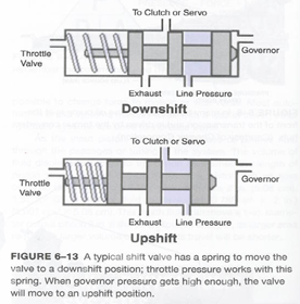
Figure 27 illustrates a downshift valve balanced between throttle valve pressure and governor pressure. In this case, throttle valve pressure overcomes governor pressure, producing a downshift under heavy acceleration. The same principle applies in reverse: as vehicle speed rises under light acceleration, governor pressure increases and eventually overcomes throttle pressure, moving the valve to direct oil pressure into a clutch or band and create an upshift. A spring holds the valve in position at low load and speed, preventing an undesired upshift when the vehicle is stationary or just beginning to move.
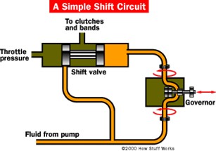
Figure 28 shows how the governor receives line pressure from the pump and regulates it to the shift valves. Driven by the output shaft, the governor spins faster as road speed increases, sending progressively more pressure until a shift valve slides and applies a clutch or band for an upshift.
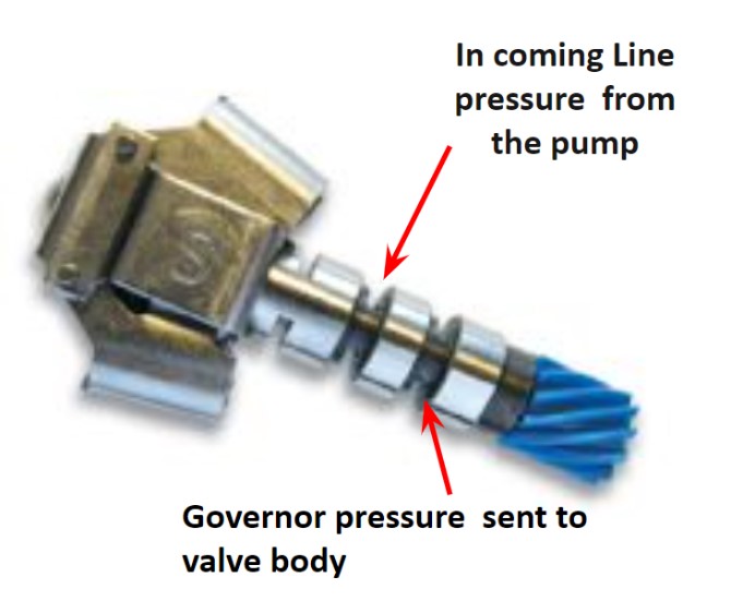
Figure 29 depicts a governor from a GM THM 350 three-speed transmission. Inside the polished housing is a spool valve, while the blue drive gear meshes with the transmission’s output shaft gear. The gold-colored section contains centrifugal weights that move the spool valve in proportion to rotational speed, thereby regulating how much fluid passes through. Line pressure enters the assembly and exits as governor pressure.
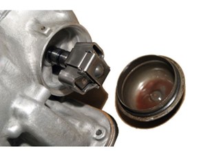
Figure 30 identifies the governor’s physical location. It sits under a round cap at the rear of the transmission, a placement consistent across most manufacturers.
In practice, governor pressure should correlate directly with vehicle speed. A useful diagnostic guideline was that governor pressure approximated 10 psi at 10 mph, 20 psi at 20 mph, and so forth. This relationship made governor pressure testing an important part of transmission troubleshooting.
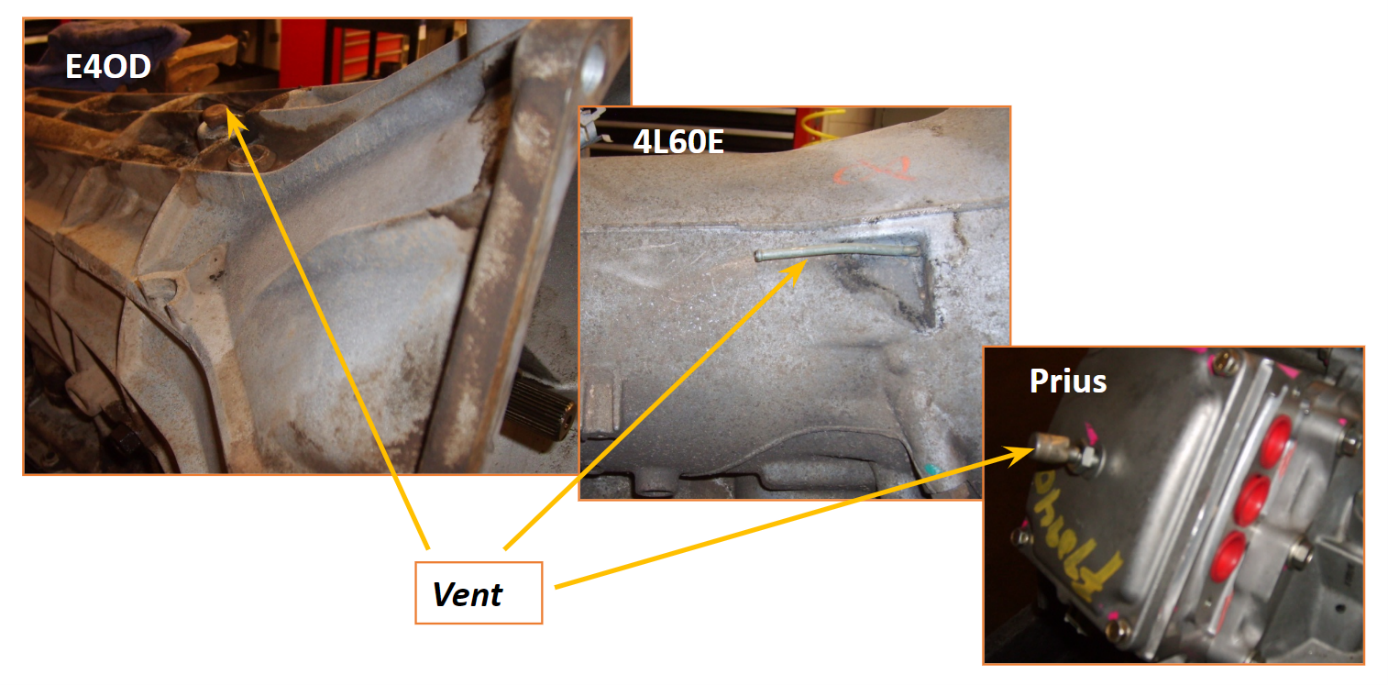
Figure 31 highlights transmission vents. Venting serves two important purposes:
It allows atmospheric pressure to assist fluid flow into the suction side of the transmission pump.
It prevents excessive pressure buildup by releasing hot gases.
If pressure within the case rises too high, it can force fluid past seals and cause leaks. While seals and gaskets naturally wear with time, a plugged vent is another common reason for fluid leaks. Proper venting ensures both consistent pump operation and protection against pressure-related failures.
Lubrication Circuit
The other half of the hydraulic system is the lubrication circuit. Every automatic transmission includes one, and while simpler than the high-pressure side, it is still a carefully designed system.
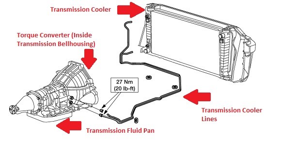
This circuit directs fluid from the transmission pump to either the torque converter or the cooler. Fluid routed to the torque converter keeps it filled and allows the converter clutch to engage or disengage. Fluid directed to the cooler passes through a heat exchanger inside the radiator, and in some cases, through a separate air-to-oil cooler for additional cooling.
After leaving the cooler, this fluid becomes lubrication oil. It flows through dedicated passages that supply gearsets, bearings, and other rotating components, ensuring they remain properly lubricated during operation.
Control valves regulate how fluid is distributed between these sub-circuits—the torque converter, the cooler, and the lubrication passages.
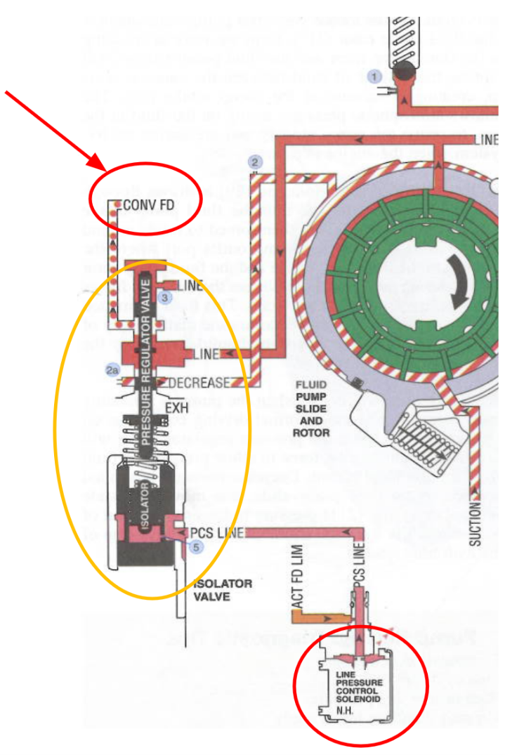
The lubrication circuit begins at the pressure regulator valve (circled in yellow). Here, mainline fluid from the pump is tapped off. Part of this fluid is directed into the Converter Feed (CONV FD) line. The pressure regulator valve and the LPC solenoid (circled in red) continue working together to regulate mainline pressure as explained earlier.
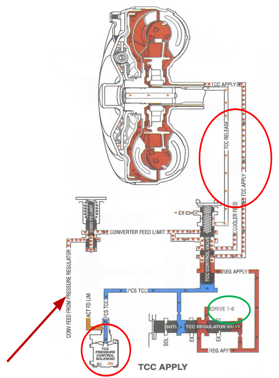
Figure 34 shows the converter feed circuits labeled TCC APPLY and TCC RELEASE. When the TCM determines that the torque converter clutch should apply, the TCC Pressure Control Solenoid (TCC PC Solenoid) (circled in red at the bottom) allows fluid from the “Drive 1–6” circuit (circled in green) to enter. This fluid becomes REG APPLY pressure, which the TCC Control Valve then directs into the TCC APPLY passage and into the converter.
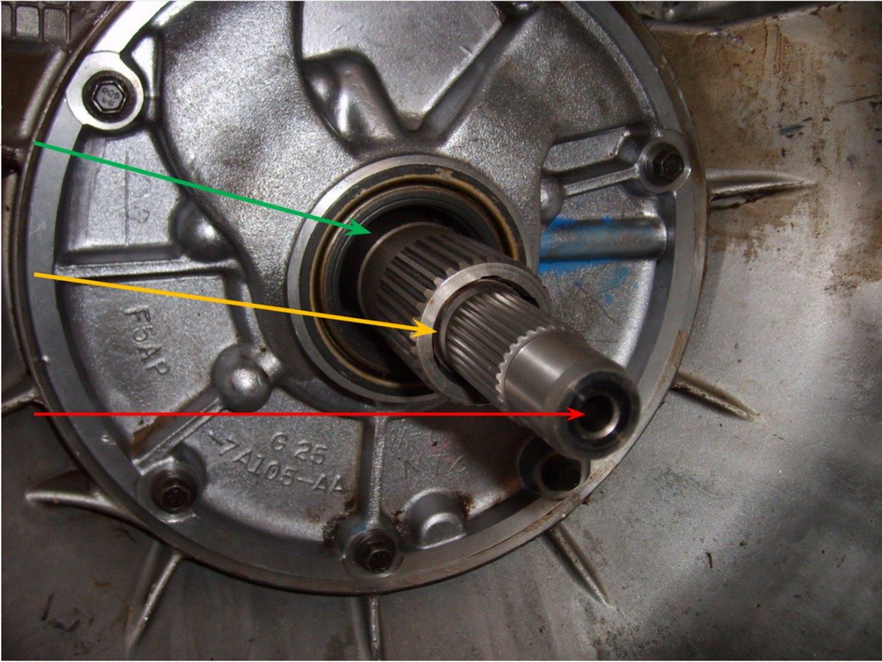
When TCC APPLY fluid enters the converter, it flows between the converter hub and the stator shaft (green arrow, Figure 35). From there, fluid pressure builds behind the TCC clutch plate inside the converter. This pressure forces the clutch plate against the converter cover, engaging the clutch.
At the same time, the TCC RELEASE circuit provides a path for fluid pressure to exit during clutch engagement. To release the clutch, the TCC PCS solenoid signals the TCC Control Valve to drop. This action allows fluid from the Converter Feed Limit circuit into the TCC RELEASE passage. Pressure then builds in this passage, which disengages the clutch. The yellow arrow in Figure 35 shows where fluid exits during release—between the stator shaft and the input shaft.
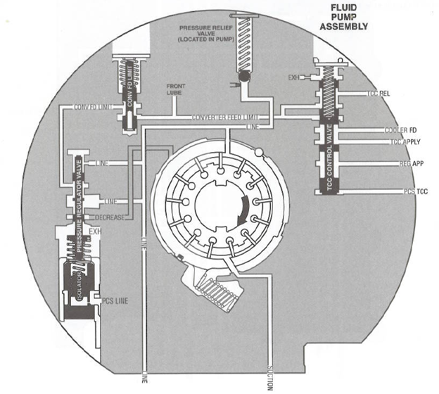
This figure identifies the location of the pressure regulator valve inside a GM 6L80E: within the transmission pump housing. The LPC solenoid, located on the valve body (not pictured), works with the regulator valve to maintain system pressure. Also within the pump housing are the Converter Feed Limit Valve and the TCC Control Valve.
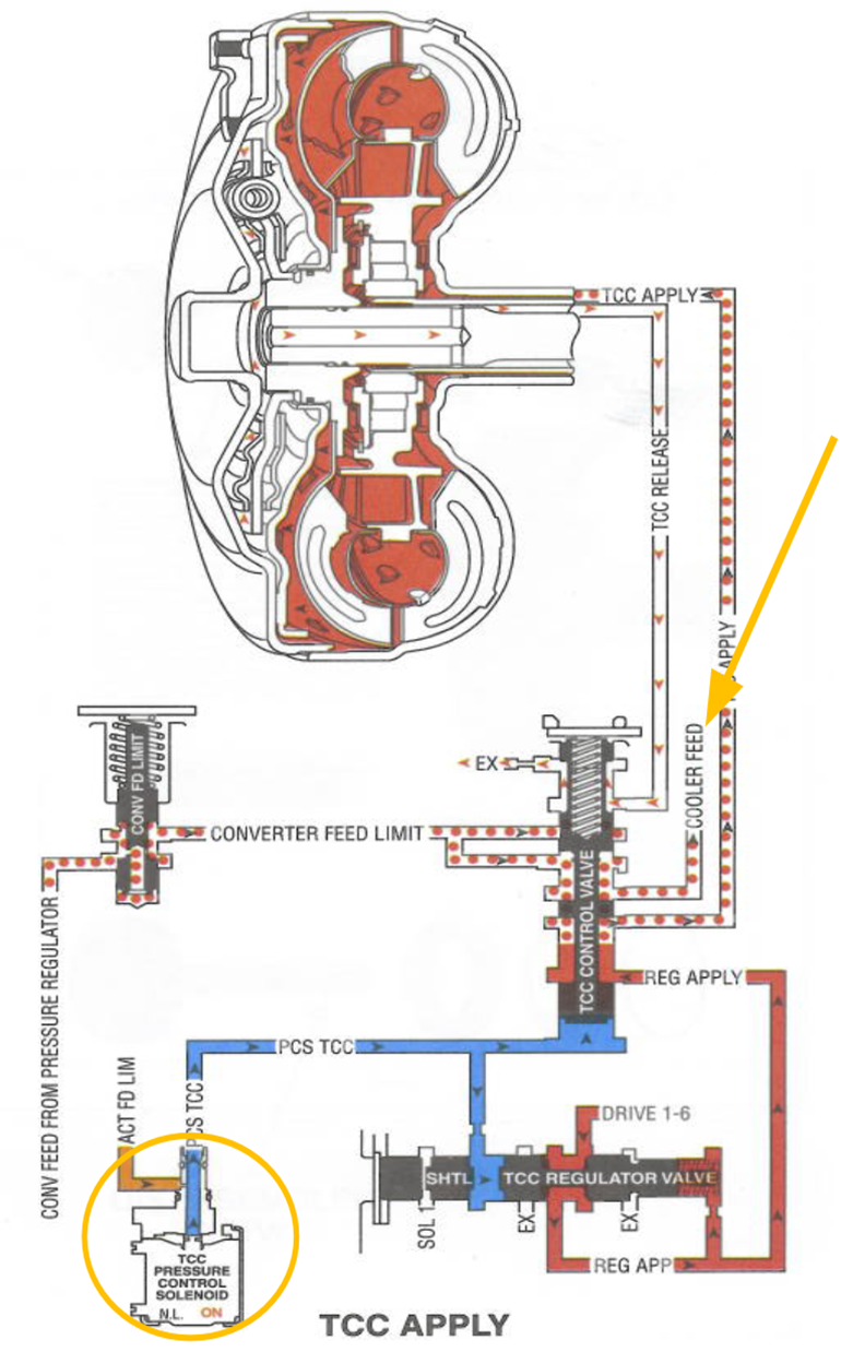
Lubrication flow begins when the TCC Control Valve directs fluid to the Cooler Feed circuit (orange arrow). Fluid is almost always routed through the cooler unless a transmission thermostat restricts flow, as discussed earlier. This cooling path is active regardless of whether the TCC is applied or released.
When the PSC TCC line (blue) is pressurized, the TCC Control Valve shifts upward. This opens flow from the Converter Feed Limit circuit into the Cooler Feed circuit. At the same time, fluid from REG APPLY (red) is directed into the TCC APPLY passage. With this, the converter clutch engages. This setup demonstrates how closely the converter and cooler circuits interact.
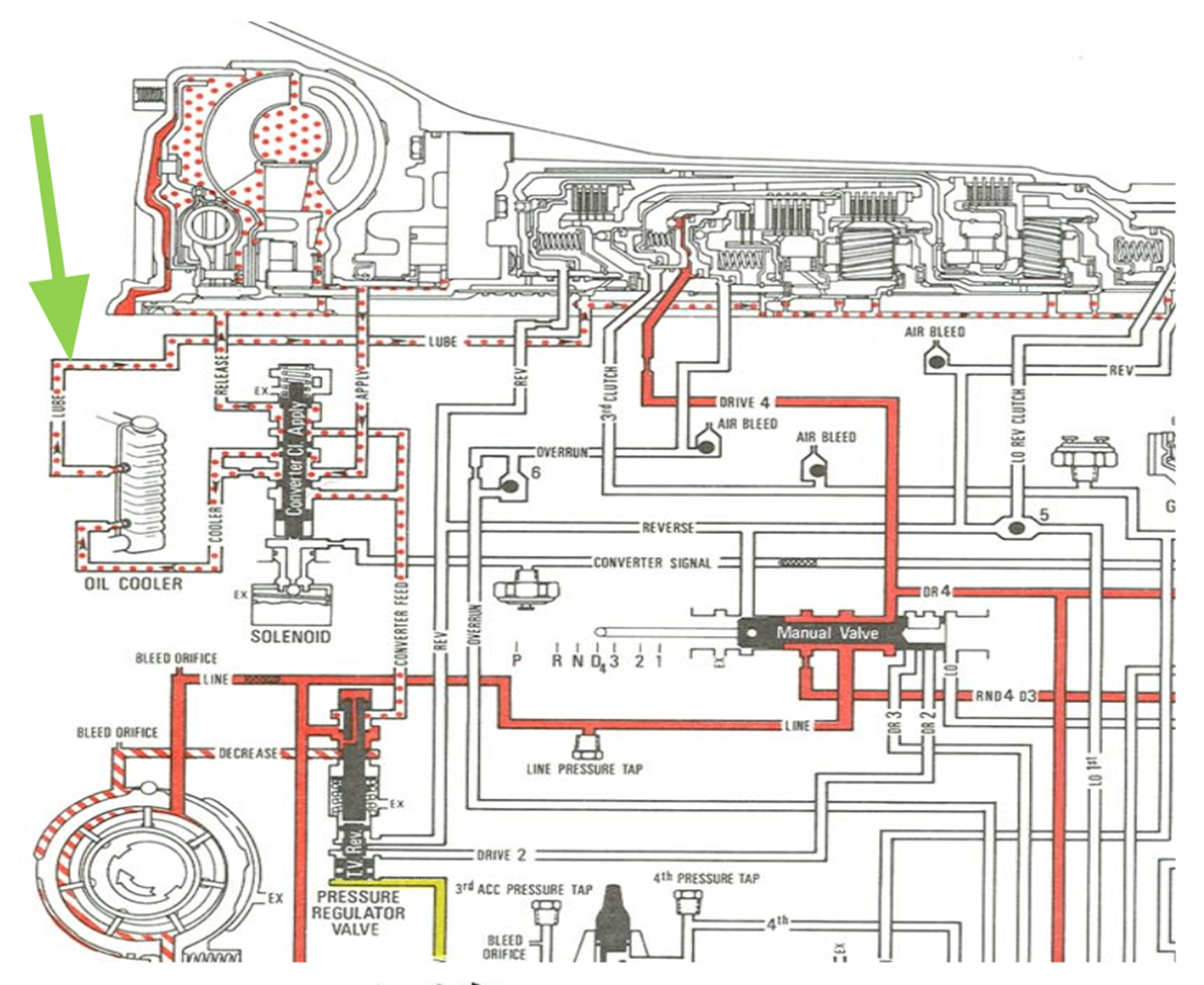
Once cooling and lubrication are complete, fluid travels through lube passages (green arrow) to gears and bearings before draining back to the sump. From there, it is available to be picked up by the pump again and sent back into the valve body or the lubrication circuit.
As introduced earlier, the lube circuit serves three purposes:
Cooling the transmission fluid.
Supplying charge oil to the torque converter and its clutch.
Lubricating gears, bushings, and bearings throughout the transmission.
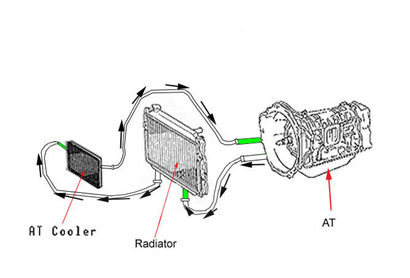
Figure 39 illustrates a complete cooler system as commonly seen in automatic transmission vehicles.
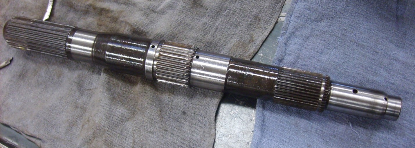
It might be difficult to visualize how oil reaches the various parts of a transmission. Lube fluid is directed through passages in the transmission case and then routed into several hollow channels within the transmission’s main shaft.
Figure 40 shows the main shaft drilled holes. Fluid passes through these passages and exits through the holes, which are precisely machined to direct lubricant to critical areas of the transmission.
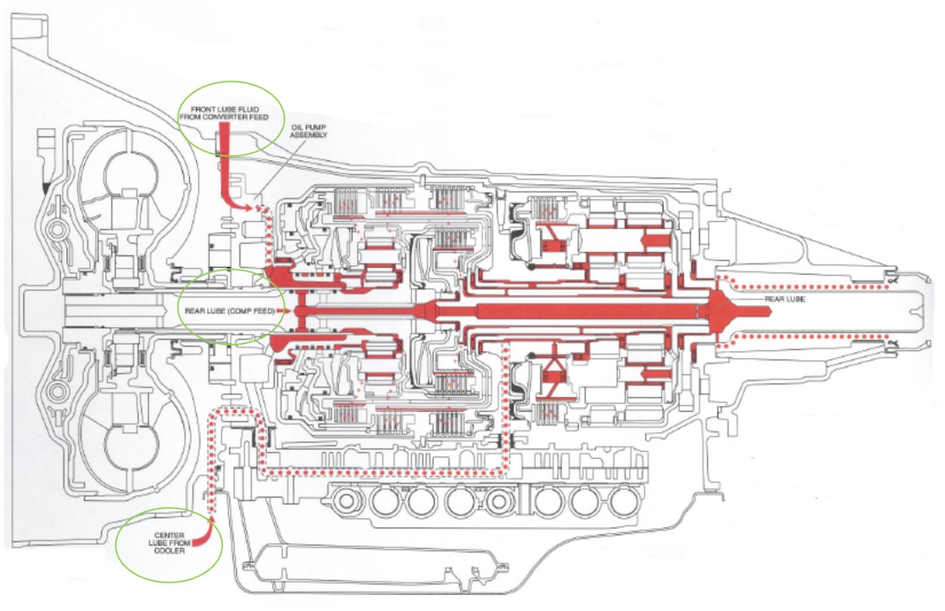
Figure 41 illustrates the lube passages in a 6L90 transmission. Fluid is fed into both the input and main shafts, then branches outward to supply vital oil flow to components such as bushings, clutch drums, and planetary gear sets.
Circled in green (from top to bottom), lube originates from three sources:
The converter feed circuit
The input shaft “COMP FEED” hole (sourced from the converter)
The cooler circuit
Ensuring that moving components receive sufficient lubrication is critical to transmission life. Without lubricant, bushings, gears, and other parts quickly overheat and wear, leading to premature failure—similar to what happens in an engine without proper oil.
Aftermarket Solutions
To address weaknesses in factory designs, aftermarket companies such as Sonnax, Superior, and Transgo offer products that enhance lubrication, cooling, and shifting.Let’s explore this by going to Superior’s site and searching for a product that they manufacture for a number of Ford four- and six-speed transmissions.
Visit their website: https://superiortransmission.com
Go to the yellow ‘Search by Transmission’ box.
Under the manufacturer, choose ‘FORD.”
Under Categories, choose ‘Sure-Cool Thermostatic Bypass kit.’
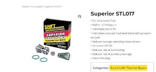
For example, Superior manufactures a Sure-Cool Thermostatic Bypass Kit (part STL017) for a range of Ford four- and six-speed transmissions including the 4R70W, 4R75E/W, 6F35, 6R80, 6R80/90, and 6R90. This kit prevents overheating caused by a stuck thermostat valve in the OEM housing.
Such products are widely respected in the transmission repair industry, and shops often recommend or install them when servicing or replacing transmissions.
To close this chapter, we need to look at the concept of adaptive strategy. Inside a transmission, adaptive strategy refers to the TCM’s ability to automatically adjust for normal wear of transmission components. As clutches age, their apply and release timing can vary. To compensate, the TCM alters clutch pressures by commanding the LPC/EPC solenoid to make corrections.
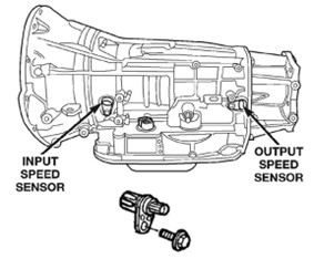
This is very similar to the PCM’s adaptive fuel trim in engines, where it fine-tunes fuel delivery as components wear. In transmissions, the TCM monitors every shift using ISS (Input Shaft Speed) and OSS (Output Shaft Speed). If a shift happens too slowly or too quickly, the TCM recalculates the required pressure and updates it in memory.
The result is a system that constantly self-adjusts for smooth, consistent, and precise shifting over the life of the transmission.
Chapter Review
A transmission’s hydraulic system is controlled by electrical solenoids. Automatic transmissions function through a combination of mechanical, hydraulic, and electrical principles. Hydraulic operation begins at the pump, which supplies pressurized fluid to every part of the transmission.
The valve body and TCM work together to coordinate shift timing as the vehicle operates. Not all shift solenoids function the same way—some are normally open at rest, while others are normally closed. Valve body functions are highly precise and depend on programmed parameters.
To deliver effective torque to the drive wheels, all transmission components must work together, supplying exact pressures to each shift element.
Aftermarket manufacturers provide parts that can improve transmission performance, cooling, and reliability. These products are often valuable to consumers and frequently recommended by transmission repair shops.
Finally, a transmission’s adaptive strategy is the TCM’s ability to adjust shift quality over time. By monitoring input and output shaft speeds, the TCM modifies hydraulic pressure to compensate for component wear. This ensures smooth, consistent, and precise shifting throughout the life of the transmission.
Sources
Automatic Transmissions and Transaxles, 7th Ed. — James D. Halderman, 2017
Hydra-Matic 6 Speed RWD Technician’s Guide — Powertrain Group, General Motors Corporation, 2005
Manual Drivetrains and Axles, 7th Ed. — James D. Halderman and Tom Birch, 2015
Peerless Engineering — “Hydraulic Pumps: Fixed vs. Variable Displacement” http://peerlessengineering.com/blog/hydraulic-pumps-fixed-vs-variable-displacement/
Sonnax — “Anatomy of a Transmission: Oil Flow in the Pump, PR, Converter, Cooler & Lube Circuits” https://www.sonnax.com/tech_resources/131-anatomy-of-a-transmission-oil-flow-in-the-pump-pr-converter-cooler-lube-circuits