Forming Processes
The wide variety of parts made by the thermoforming process has led to the development of several modifications of the basic thermoforming technique to optimize the making of particular shapes and to improve upon some of the inherent problems associated with thermoforming. Thermoforming processes can be divided into three general methods; vacuum forming, pressure forming, and twin-sheet forming. The standard process for each of these thermoforming methods is quite simple and straightforward. In addition, each of these basic methods can be modified to facilitate making specific shapes and to achieve other design requirements. The modifications and their advantages and disadvantages will be analyzed, and each of the major methods will be discussed in detail in terms of sheet thermoforming. Also considered will be equipment, plant considerations, normal operations, troubleshooting, and part design.
14.2.1. Vacuum Forming
Vacuum forming is the simplest thermoforming technique and the one most commonly envisioned when thermoforming is discussed. All thermoforming techniques were once referred to as vacuum forming. Today, the term is applied only to those processes that use vacuum as the force that draws the heated plastic against the mold. Vacuum forming is used when only the outside of the part (the side against the mold) must have detail or close tolerances. The inside surface of the part is defined only by the air (beyond what finish was present on the unmolded extruded sheet). Photo 14.2 shows a vacuum-formed part in the vacuum molding machine.

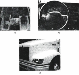
Photo 14.1 Thermoformed products. (a) Thermoformed bath tubs. (b) Thermoformed instrument panel. (c) Thermoformed vehicle fender. ((a) Courtesy of The Home Depot, Provo, Utah; (b), (c) Courtesy of BYU)
Fundamental or Straight Vacuum Forming. The simplest of the vacuum forming techniques is sometimes called fundamental or straight vacuum forming to emphasize that only the basic process is being used. Other techniques are discussed later. The method has also been called one-step thermoforming because molding is accomplished in a single step after the material has been heated.

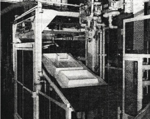
Photo 14.2 Standard vacuum forming machine. (Courtesy of Brown Machine)
In this processing technique the material is clamped into a frame, which holds the material around its periphery. The material is then heated and when it begins to sag (the sag point), it is transferred so that it seals against the mold. In this process the mold is a female mold or cavity mold, although in other, related processes male molds are used. A vacuum is immediately applied to the back of the mold through an air space. The vacuum connects with the mold cavity through small vent holes that are drilled through the mold walls. When the vacuum is applied, the plastic material is drawn against the mold cavity walls. (Actually, the outside pressure of the air pushes the plastic against the mold because of the partial vacuum created between the plastic and the mold. Hence, the highest pressure that can be achieved with the vacuum technique is approximately 1 atmosphere [14.5 psi, 100 kPa].) The vacuum is continued while the material cools and takes the shape of the mold cavity. The fundamental, or straight, vacuum-forming technique is illustrated in Figure 14.1.

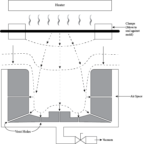
Figure 14.1 Fundamental, or straight, vacuum forming-technique.
When the sagging occurs, the center of the material moves downward and stretches near the clamp, resulting in a thinning in that region (the periphery). As the material moves against the cavity walls when the vacuum is applied, stretching then occurs uniformly over the sheet until the sheet touches the mold. Wherever the sheet touches the mold the thickness at that location becomes fixed. Further stretching must occur in the areas that have not yet touched the mold, typically in the corners. Therefore, the thinnest areas are in the corners. Other thin areas are near the clamps and also in any other area where the material must travel longer distances. Hence, uneven wall thicknesses are inherent in this technique. Because of wall-thickness variations, the depth to which a sheet can be drawn is limited. The limitation depends on both the depth of the draw and the width of the area being drawn. If the area to be drawn is narrow, the part cannot be drawn very deep. That is, as the width of the drawn area gets narrower, the depth to which the part can be drawn decreases. This relationship is defined as the draw ratio, the ratio of the depth of draw (that is, the greatest vertical distance the plastic sheet was moved) divided by the width of the drawn area. For fundamental vacuum forming, the typical draw ratio that can be achieved without ripping the part or having excessive thickness variations is about 1:1, that is, the part cannot be drawn to a distance that is deeper than the width of the drawn area.
Plug-Assist Forming. This is a special technique used to improve wall-thickness uniformity in fundamental vacuum forming. In plug-assist forming, a plug (shaping tool) is used to force the heat-softened material into the mold. Generally, the plug will not push the material completely into the mold, but, rather, only partway to a positive seating. A vacuum is then applied to draw the material against the cavity walls and complete the forming operation. This technique is shown in Figure 14.2.
The major advantage of plug-assist forming is better wall-thickness uniformity than can be obtained with vacuum or pressure forming, especially for parts with deep draws such as cup or box shapes. The plug can be used to carry material towards the areas that would have been too thin if just fundamental vacuum were used. In plug-assist forming, the initial sagging of the material is kept to a minimum. The plug is moved against the material and wherever the plug touches the material, the thickness of the material is fixed at the contact points. Therefore, by shaping the plug appropriately, the plug can "carry" some of the material toward the corners and force the areas that would be thick in fundamental vacuum forming to be stretched. (The areas that would normally be stretched during the plug-forming stage would be the center of the bottom and the sides.) Then, when the vacuum is applied, the material moves outward off the plug and stretches uniformly until the material makes contact with the mold. As with fundamental vacuum forming, this contact first occurs at the center of the bottom and along the walls. The thickness then becomes fixed at those locations and stretching occurs in the corners and other locations not yet in contact with the mold. In the case of plug-assist forming, however, the material in the corners is thicker than in the fundamental vacuum case and can stretch more without becoming too thin. Therefore, the plug results in a retention of the thickness in the corners for a portion of the forming process such that the finished part is more even overall. Many fundamental vacuum-forming and pressure-forming machines have the capability of plug-assist forming.
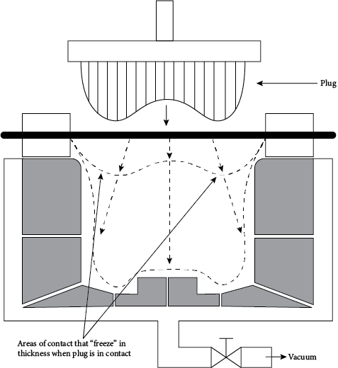
Figure 14.2 Plug-assist forming
The advantage of plug molding over fundamental vacuum forming can be seen quantitatively by comparing the draw ratio that can be safely achieved in each of the processes. As discussed previously, the draw ratio for fundamental vacuum forming is 1:1. That ratio can be increased in plug-assisted forming to 2.5:1. That is, the depth of draw can be 2.5 times greater in plug-assisted forming for the same part width and allowable thickness variation.
Plugs can be made of metal, wood, or thermoset plastics. To prevent premature cooling of the material, especially if the plug is metal, the plug is usually heated to a few degrees less than the temperature of the plastic. The plug should be 10 to 20% smaller in length and width than the female cavity.
Reverse Draw Forming. The reverse draw forming technique (also called invert forming, pillow forming, or billow forming) is used when very deep draws are needed. It is a special technique within the vacuum forming method. In this technique, the material is heated to the sag point and then blown in a direction away from the mold. The purpose of this blowing or reverse drawing is to thin the material in the center of the sheet that is the thickest area during fundamental vacuum and pressure forming. The size of the bubble is often controlled automatically by an electric eye. When the bubble reaches the correct size, the pressure is stopped and a plug presses on the material to force it back into the mold. As with normal plug-assist molding, the points of contact with the plug are fixed in thickness and all other areas are thinned by the movement of the plug as it further stretches the material. After the plug has moved the corner material close to the walls of the mold, a vacuum is activated through the mold to draw the plastic against the mold walls. The stretching occurs in the normal way with the material traveling the furthest being stretched the most. The molding is completed by cooling the material against the mold. The reverse draw forming method is shown in Figure 14.3.
This technique has the advantage over plug-assist molding in that an additional stretching step has been added (the reverse drawing step), which allows even better control over the part thicknesses. The penalty for this improved control is a longer mold cycle. Fine adjustments in the thickness of the part can be achieved by varying (1) the temperature at which the material is blown, (2) the size of the bubble, (3) the size of the plug, (4) the shape of the plug, (5) the speed of travel of the plug, and (6) the timing of the imposition of the vacuum or air pressure. As might be expected, the permissible draw ratio of the reverse draw method is better than either the straight vacuum forming or plug-assist methods. Whereas straight vacuum forming has a typical draw ratio of 1:1 and plug-assist has a ratio of 2.5:1, reverse draw forming in-creases the permissible draw ratio to 3:1.
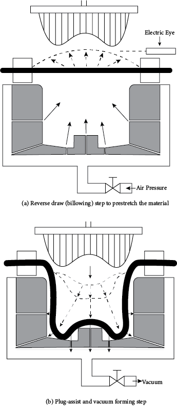
Figure 14.3 Reverse draw forming or billow forming.
Drape Forming. Drape forming is the term applied to thermoforming using a male mold. In this technique the material is clamped and heated to the sag point and then forced over the mold by moving the material onto the mold. Simultaneously, vacuum is applied through vent holes in the mold, thus drawing the part tightly against the outside surface of the mold. The part is cooled in contact with the mold. The drape forming technique is shown in Figure 14.4.
In drape forming the movement of the mold and material together is much like the movement of a plug in plug-assist forming except that in plug-assist forming the plug is smaller than the size of the finished part and, of course, the plug withdraws from the part before final forming is done. Nevertheless, the actions of the two processes are similar.
Drape forming can be combined with a lateral stretching technique to achieve a biaxially oriented part. When this technique is used, the heated material is stretched outward by the clamping mechanism before it is forced over the male mold. This gives orientation to the sheet. When the sheet is then forced over the male mold, further orientation occurs. The resulting part is, therefore, stronger in the oriented directions than it otherwise would be.
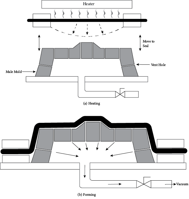
Figure 14.4 Drape forming on a male (plug) mold.
The most obvious use of male molds is when the inside of the part needs to have good surface definition or detail and dimensional control. This is achieved because the material is forced against the outside of the mold, which becomes the inside of the part. Parts made by drape forming would include those for which a grain surface is required on the inside—bathtubs and spas and other deeply drawn cup-shaped parts.
A major advantage of drape forming over forming in a cavity mold is the greater depths of draw that can be achieved without excessive thinning. The part is forced over the mold with relatively little thinning. Therefore, when the final forming takes place, the thickness uniformity is much better than could be achieved with a cavity mold. Typical draw ratios would be 3.5:1. Another advantage of drape forming is the lower cost of making a plug mold versus a cavity mold. It is easier to cut and polish on the outside of a surface than in a cavity. Plug molds are also more easily damaged, so additional care in storage and use is required. Just as plug and pressure forming are faster than fundamental vacuum forming because the material is forced into contact with the mold by fairly high pressures, so too is drape forming faster than fundamental vacuum forming. Therefore, drape molding is favored for parts that are extremely sensitive to the mold cycle.
A disadvantage of drape forming is that the part has a greater tendency to wrinkle as it is drawn over the mold. Also, it may stick more. Another dis-advantage of drape forming is that more space is required around the mold, so the trim (scrap) is greater. This requirement arises from the need to clamp the material on the outside of the mold. Therefore, very high production lines in which many molds are used to form similar parts (such as low-cost cups) would use female molds rather than male molds so that the number of parts molded in a set area of sheet would be higher.

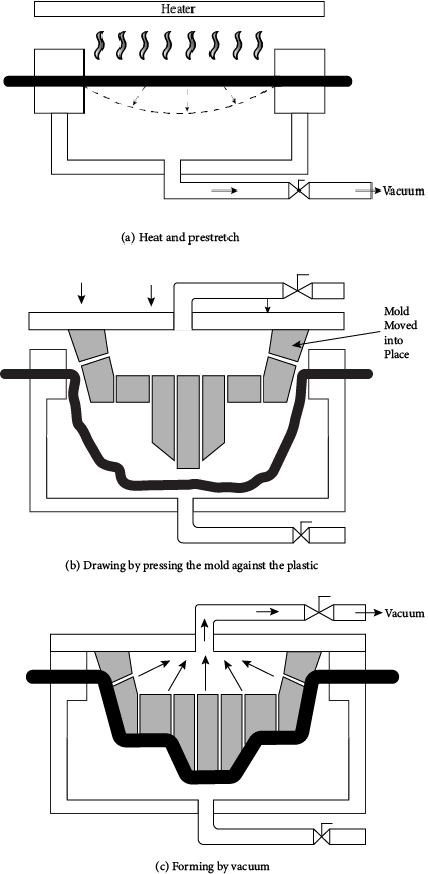
Figure 14.5 Snap-back forming showing prestretching, drawing, and forming steps.
Snap-back Forming. Snap-back forming is another variation on vacuum forming. It can be considered as a combination of vacuum, plug-assist, billow, and drape forming. In snap-back forming, the material is heated to the sag point and then drawn slightly into a vacuum box below the part. This is like reverse draw (pillow) forming in the opposite direction. This prestretching thins the center of the part and is usually about one-half to two-thirds of the total draw that the part will receive. A second step is then activated to give more draw. The plug mold is pressed against the material to draw it farther. During this drawing step, the thickness of the center of the material is fixed by con-tact with the mold and thinning occurs near the edges. Finally, the part is finish formed by applying a vacuum through the plug mold and causing the part to "snap back" against the outside of the plug mold. The part cools against the plug mold to take its final shape. The snap-back forming process is depicted in Figure 14.5, where the prestretching, drawing, and forming steps are shown. If the part is oddly shaped, such as having a very long draw in just one area, the vacuum box can be shaped to accommodate the unusual features.
The uniformity of wall thickness is very well controlled by this snap-back forming process and its popularity is increasing in spite of the typically longer cycle times that are required. The typical draw ratio increases to 4:1 by using this technique.
14.2.2. Pressure Forming
The second of the major thermoforming methods is pressure forming. This technique forms the heated plastic material in a female mold as does vacuum forming. In this case, however, positive air pressure on the top of the plastic is used to force the material against the mold, rather than just vacuum pressure.
In pressure forming the material is clamped and heated just as with fundamental vacuum forming. The softened sheet is transferred to the molding area and a seal is made so that the upper chamber, above the plastic, is airtight. The material is also sealed against the mold as is done with vacuum forming. Air pressure is then introduced into the area above the softened plastic, usually through an air baffle to ensure that the air is evenly distributed across the surface of the plastic. The air pressure forces the plastic against the mold. The vent holes are still used to ensure that no air is trapped between the plastic and the mold. This technique is shown in Figure 14.6 and is similar to blow molding. The air pressure used is generally 14.5 to 300 psi (100 to 2000 kPa, 1-20 bar), and it should be applied as quickly as possible to prevent the sheet from cooling or from excessive sagging. The advantage of the pressure method is that mold cycles can be faster than with fundamental vacuum forming, the sheet can be formed at a lower temperature because the forcing pressure is higher, and greater dimensional control and part definition can be obtained. Vacuum pressure is limited to about 1 atmosphere, whereas the positive pressure in pressure forming can be much higher. When a positive pressure source is used, the pressure can be created much more rapidly and generally at lower cost. Although not capable of the part complexity of injection molding, the surface quality and detail characteristic of injection molding can be readily achieved using pressure forming. Hence, some parts that might otherwise be made by injection molding can be made by pressure thermoforming. Also, pressure forming can often be used to make prototypes of parts that will eventually be made by injection molding. Even within the limitations of complexity just mentioned, the level of detail that can be obtained in pressure forming is much higher than in any other thermoforming method. Surface details, such as textures and patterns, are quite easily obtained. Undercuts, which are somewhat difficult to define using vacuum thermoforming, can also be well defined using pressure.

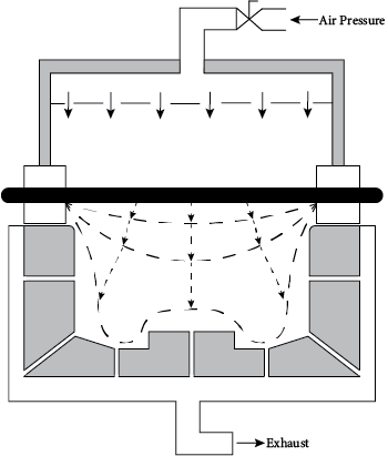
Figure 14.6 Pressure forming.
As with vacuum forming, some special techniques modify the basic forming method to achieve specialized products. These modified techniques all use pressure to force the heated plastic into the shape desired but differ in the way the pressure is applied and the constraints within which the part is molded.

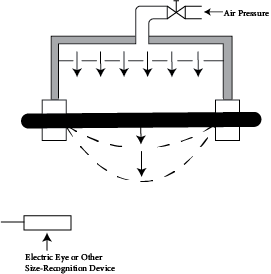
Figure 14.7 Free forming or free blowing.
Free Forming. In some products, especially those were very high optical quality is required, the forming is done without a mold. (Touching the mold can result in undesirable changes in the surface quality of the part.) This technique is called free forming or free blowing, illustrated in Figure 14.7, so pressure alone is the shaping force.
In free forming the part is expanded with air pressure, much as it would be in the first step of reverse draw forming. The size of the bubble is often monitored by an electric eye. When the bubble reaches the desired size, the air pressure is reduced to a level that maintains the size of the bubble while the part cools.
The complexity of shapes of parts made by free forming is much more limited than could be made if a mold were employed. However, some shape control can be achieved by varying the shape of the clamping ring. For instance, if the clamping ring is a circle, the part will be a hemisphere. If the shape of the clamping ring is teardrop, the resulting part will be elongated and streamlined. This streamlined shape is often used for canopies for racing vehicles where high optical clarity is needed. (Forming against a mold can cause some loss in optical clarity.)
Matched Die Forming. Some parts, especially those with very complicated shapes, can best be formed if both plug and cavity molds or dies are used together. These molds must be mated or matched so that they fit together without interference and leave only the space between them for the material. In matched die forming the clamped material is heated to the sag point and is then transferred to a molding station where the plug and cavity molds are immediately brought together to squeeze the material. Vent holes in both molds allow any air that might be trapped between the material and the molds to escape. No vacuum or air pressure is used during this forming process. The material is mechanically pressed into the shape de-fined by the matched molds and is allowed to cool while the molds continue to press against it. Matched die forming is depicted in Figure 14.8.

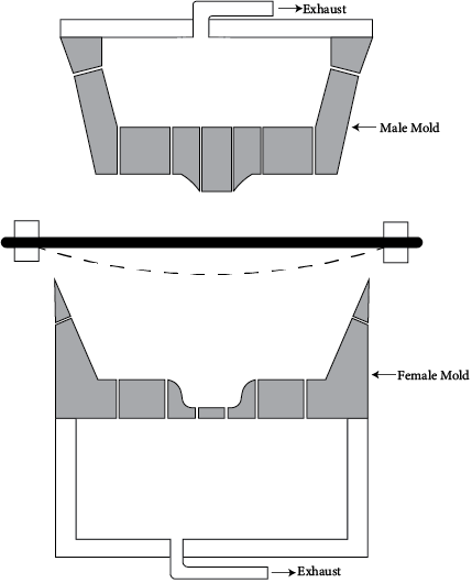
Figure 14.8 Matched die forming.
The pressures involved in matched die forming are somewhat higher than in other thermoforming methods but are not nearly as high as in injection or blow molding nor as high as in matched die compression molding, which is discussed in Chapter 18. The lower pressures result from the soft and pliable state of the plastic material when it is formed and the relatively small distances over which the material must be moved during the forming process.
Matched die forming is used most often for parts that do not have large draws. Very large parts can also be molded effectively using matched die forming. Matched die forming is also used for parts that must have excellent definition or dimensional control on both sides.
An interesting modification of matched die molding uses a softer material for one of the sides in the matched die. In one common option, the softer surface is an elastomeric pad. Although precise definition decreases when the soft tool is used instead of the hard tool, the elastomeric pad is less expensive and does not require the same precise alignment and care that is needed when both of the matched dies are hard. In other words, the elastomeric pad gives many of the benefits of matched die molding but with less cost and improved molding operation flexibilities.

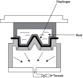
Figure 14.9 Diaphragm molding.
Another soft tooling technique utilizes a bag of fluid (usually water) as one side of the matched die mold. This technique, illustrated in Figure 14.9, is called diaphragm molding since the fluid is contained within a bag or diaphragm. A vacuum is sometimes used on the back of the hard tooling side to achieve better definition than could be obtained with just the pressure of the fluid.
Mechanical Forming. Mechanical forming is, perhaps, the simplest of all the thermoforming techniques. In this method the heated sheet material is formed by mechanically pressing it using forming tools (not molds) to give the desired shape. For instance, if a sheet is to be attached inside a bracket, the bracket itself can be used as the shape-defining device. The plastic material would simply be cut to the appropriate size and then heated to the sag point. While still hot, the material would be pressed against the inside of the bracket to create the desired shape. The pressing could be done by a roller, a block, or any other convenient instrument that will apply a relatively uniform pressure on the material as it takes the shape desired. The material is then cooled in place.
Another example of mechanical forming would be the wrapping of a heated plastic sheet around a rod. In this case the material is cut to the desired size and one end is inserted into a clamp attached to the rod. The material is heated to the sag point and then pressed onto the rod as the rod rotates. The material is again cooled in place.
Examples of forming in a bracket and around a rod are illustrated in Figure 14.10.

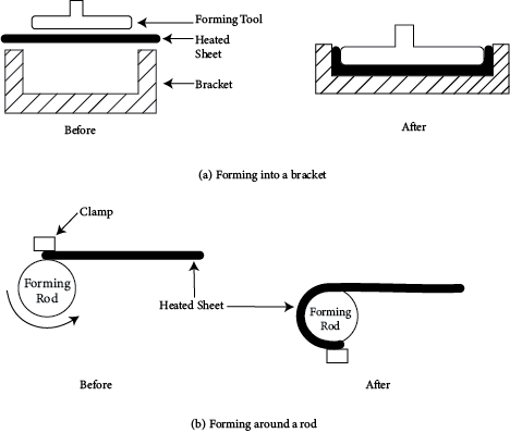
Figure 14.10 Mechanical forming for a bracket and a rod.
14.2.3. Twin-Sheet Thermoforming
The third of the major thermoforming methods, along with vacuum forming and pressure forming, is twin-sheet thermoforming. This process allows thermoforming to be used to make parts that contain hollow regions. The process is illustrated in Figure 14.11.
This process requires two sheets of thermoplastic material. The sheets need not be the same plastic but, rather, need only be two plastics that will weld together. Such plastics are sometimes described as "compatible for twin-sheet thermoforming." The plastic sheets are heated separately (which allows for different heating conditions should the sheets be different). When both sheets have reached their sag temperatures, they are moved into two separate molds and vacuum formed. Any of the techniques of vacuum forming can be used, but straight vacuum forming is the most common and is the one illustrated in step 2 of Figure 14.11.

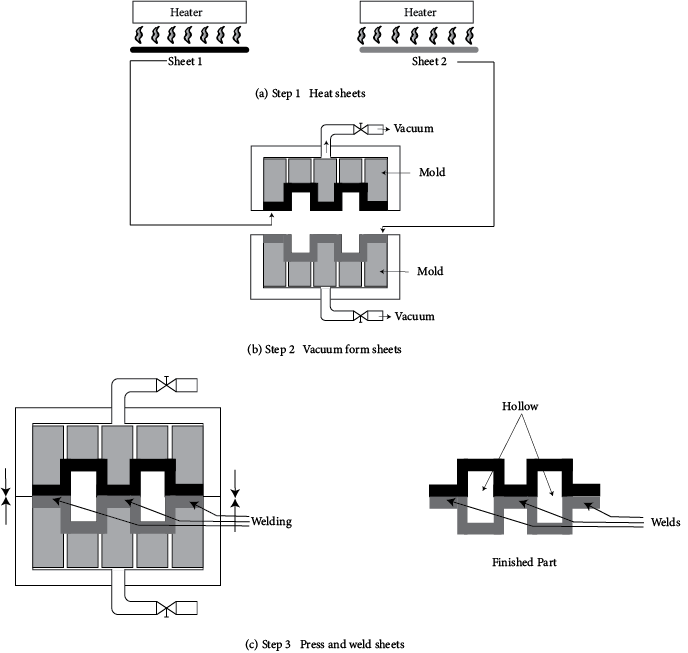
Figure 14.11 Twin sheet thermoforming.
A modification of normal vacuum forming now occurs. Rather than allow the parts to cool, the two shaped sheets are pressed together. Because of the shaping pattern, only certain regions of the two parts will touch. These are the regions in which welding occurs. Sometimes the heat content of the plastics is sufficient to cause the welding to occur. When that is not the case, additional energy must be added to the weld areas in some manner. A typical method of doing that is to use an ultrasonic welder, but many other methods are also acceptable, including just additional localized heating.
After welding has occurred, the parts are cooled and withdrawn from the molding press. The parts will have some hollow areas and some welded joints. If desired, the hollow areas can be foam-filled to achieve additional rigidity or thermal insulation capability.
Because twin-sheet thermoforming makes hollow parts, it can be considered competitive with blow molding and rotational molding. The advantages of twin-sheet thermoforming over both the other methods are the low cost of the thermoforming tooling, the higher rigidity that can be achieved because of the ability to have many weld points, and the ability to choose different materials for each side of the part. The disadvantages are that the weld lines are points of potential weakness and the size of the hollow areas are limited by the depth to which the part can be drawn. However, the total area of the parts can be quite large, with parts of 12 feet x 12 feet not uncommon. Another interesting advantage of twin-sheet thermoforming is the ability to add inserts between the sheets just before they are pressed together. These inserts could be, for instance, mechanical fastening devices for external fastening or special strengthening supports.
Some of the most common applications of twin-sheet thermoformed products are pallets, carrying cases, camper shells, and appliance bodies (such as refrigerators). The process can also be used conveniently as a prototyping method for blow molding.